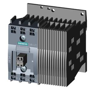
| | SOLID-STATE CONTACTOR 3-PH 3RF3 AC53 9.2A 40 DEGREES C 48-600V / 24V DC 2-PH. CONTROLLED INSTANTANEOUS SPRING-LOADED TERMINALS |
| |
| General technical data: |
| product brand name | | SIRIUS |
| product designation | | solid-state motor contactor |
| Protection class IP | | IP20 |
| Insulation voltage / rated value | V | 600 |
| Installation altitude / at a height over sea level / maximum | m | 1,000 |
| Ambient temperature | | |
| | °C | -55… +80 |
| | °C | -25… +60 |
| Resistance against shock | | |
- according to IEC 60068-2-27
| | 15g / 11 ms |
| Resistance against vibration | | |
- according to IEC 60068-2-6
| | 2g |
| Resistance against the impulse current / rated value | A | 600 |
| Active power loss / total / typical | W | 16 |
| Item designation | | |
- according to DIN 40719 extendable after IEC 204-2 / according to IEC 750
| | K |
- according to DIN EN 61346-2
| | Q |
| Product function | | instantaneous switching |
| |
| Main circuit: |
| Number of poles / for main current circuit | | 3 |
| Number of NC contacts / for main contacts | | 0 |
| Number of NO contacts / for main contacts | | 2 |
| Operating frequency | | |
| | Hz | 60… 50 |
| Operating voltage | | |
- at 60 Hz / at AC / rated value
| V | 48… 600 |
- at 50 Hz / at AC / rated value
| V | 48… 600 |
| Operating current | | |
| | mA | 500 |
- at AC-3 / at 400 V / rated value
| A | 9.2 |
| Working area related to the operating voltage | | |
| | V | 40… 660 |
| | V | 40… 660 |
| Service power / at AC-3 / at 400 V | | |
| | kW | 4 |
| Derating temperature | °C | 40 |
| Tolerance of the line frequency | Hz | 5 |
| Relative symmetrical tolerance / of the operation frequency | % | 10 |
| I2t-level / maximum | A²·s | 1,800 |
| Voltage slew rate / at the thyristor / for main contacts | | |
| | V/µs | 1,000 |
| Block voltage / at the thyristor / for main contacts | | |
| | V | 1,600 |
| Reverse current / of the thyristor | mA | 10 |
| |
| Control circuit: |
| Type of voltage / of the controlled supply voltage | | DC |
| Control supply voltage | | |
| | | |
| | | |
| | V | 15 |
| | V | 30 |
- for DC / final value for signal<0>-recognition
| V | 5 |
| Control current | | |
| | mA | 15 |
- at minimum control supply voltage / for DC
| mA | 2 |
| |
| Auxiliary circuit: |
| Number of NC contacts / for auxiliary contacts | | 0 |
| Number of NO contacts / for auxiliary contacts | | 0 |
| Number of change-over switches / for auxiliary contacts | | 0 |
| |
| Installation/mounting/dimensions: |
| Built in orientation | | vertical |
| Type of mounting | | screw and snap-on mounting onto 35 mm standard mounting rail |
| Type of fixing/fixation / series installation | | Yes |
| Tightening torque / of the screw for fastening of the operating resource | N·m | 1.5 |
| Design of the thread / of the screw for fastening of the operating resource | | M4 |
| Width | mm | 90 |
| Height | mm | 95 |
| Depth | mm | 100.8 |
| Distance, to be maintained, to the ranks assembly | | |
| | mm | 70 |
| | mm | 50 |
| |
| Connections: |
| Design of the electrical connection | | |
| | | spring-loaded terminals |
- for auxiliary and control current circuit
| | spring-loaded terminals |
| Product function / removable terminal for auxiliary and control circuit | | Yes |
| Type of the connectable conductor cross-section | | |
| | | |
| | | 2x (0.5 ... 2.5 mm²) |
| | | |
- with conductor end processing
| | 2x (0.5 ... 1.5 mm²) |
- without conductor final cutting
| | 2x (0.5 ... 2.5 mm²) |
- for AWG conductors / for main contacts
| | 2x (18 ... 14) |
- for auxiliary and control contacts
| | |
| | | 0.5 ... 1.5 mm² |
| | | |
- with conductor end processing
| | Назад в раздел
|