| | BASIC UNIT OF THE HEATING SYSTEM CONTROL SIPLUS HCS300I DC=24V |
| product brand name | | SIPLUS |
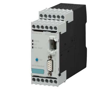
| product designation | | HCS300I heating system control |
| Design of the product | | basic unit |
| |
| Inputs/ Outputs: |
| Number of outputs / as contact-affected switching element | | 3 |
| Number of digital inputs | | 4 |
| |
| General technical data: |
| Schaltger?t / connectable | | max. 4 DM6 digital modules and 4 TM4 temperature detection modules, 1 current / voltage detection module, 1 DCM decoupling module |
| Item designation / according to DIN 40719 extendable after IEC 204-2 / according to IEC 750 | | F |
| Item designation / according to DIN EN 61346-2 | | F |
| Number of status displays | | 3 |
| Type of display / as status display by LED | | device: 4 states, BUS: 2 states, GEN.FAULT: 2 states |
| |
| Communication: |
| Design of the interface | | PROFIBUS DP |
| |
| Supply voltage: |
| Type of voltage / of supply voltage | | DC |
| Supply voltage / 1 / for DC / rated value | V | 24 |
| Operating range factor supply voltage rated value | | |
| | | 0.85… 1.2 |
| |
| Ambient conditions: | | |
| Protection class IP | | IP20 |
| Resistance against shock / according to IEC 60068-2-27 | | 15g / 11 ms |
| Conductor-bound parasitic coupling BURST / according to IEC 61000-4-4 | | 2 kV (power ports) / 1 kV (signal ports) |
| Conductor-bound parasitic coupling SURGE / according to IEC 61000-4-5 | | on supply cables: 1 kV symmetrical, 2 kV asymmetrical; on signal cables > 30 m unshielded: 1 kV symmetrical, 2 kV asymmetrical, > 30 m unshielded: 2 kV asymmetrical |
| Conducted interference as high-frequency radiation / according to IEC 61000-4-6 | | 10 V |
| Conductor-bound parasitic coupling conductor-earth SURGE / according to IEC 61000-4-5 | | 2 kV |
| Conductor-bound parasitic coupling conductor-conductor SURGE / according to IEC 61000-4-5 | | 1 kV |
| Electrostatic discharge / according to IEC 61000-4-2 | | 6 kV contact discharge / 8 kV air discharge |
| Field-bound parasitic coupling / according to IEC 61000-4-3 | | 10 V/m |
| EMC emitted interference | | IEC61131: Class A; conducted and radiated: DIN EN 55011/CISPR11 (corresponds to degree of severity A) |
| Installation altitude / at a height over sea level / maximum | m | 2,000 |
| Ambient temperature | | |
| | °C | -40… +80 |
| | °C | -25… +60 |
| | °C | -40… +80 |
| Air pressure | | |
| | hPa | 795… 1,080 |
| | hPa | 660… 1,080 |
| |
| Connections: |
| |
| connector/ bushing |
| Design of the switching output | | monostable relays |
| |
| terminals |
| Design of the electrical connection / for auxiliary and control current circuit | | screw-type terminals |
| Type of the connectable conductor cross-section | | |
| | | |
| | | 1x (0.5 ... 4 mm?), 2x (0.5 ... 2.5 mm?) |
- finely stranded / with conductor end processing
| | 1x (0.5 ... 2.5 mm?), 2x (0.5 ... 1.5 mm?) |
- for AWG conductors / for auxiliary contacts
| | 1x (20 ... 12), 2x (20 ... 14) |
| |
| Installation/mounting/dimensions: |
| Built in orientation | | any |
| Type of mounting | | snap-on fastening on 35 mm standard mounting rail or screw fastening using an additional push-in lug |
| Width | mm | 45 |
| Height | mm | 106 |
| Depth | mm | 115 |
| |
| Certificates/approvals: |
| Verification of suitability | | CE |
| |
| | |
| |
| last change: | Oct 31, 2011 |