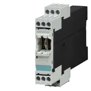
| | TEMPERATURE DETECTION MODULE TM4 HEATING SYSTEM CONTROL SIPLUS HCS300I |
| Product brand name | | SIPLUS |
| product designation | | Heating control HCS300I |
| Design of the product | | Temperature module |
| |
| Inputs/ Outputs: | | |
| Number of analog inputs | | |
| | 1 | 4 |
| | 1 | 2 |
| |
| General technical data: |
| physical measuring principal | | Sigma delta modulation |
| Number of status displays | | 3 |
| Type of display / as status display by LED | | Continuously illuminated: ready, flashing: no connection to base unit |
| Metering precision | | typically +-1 K, Pt-100 up to max. +-1.3 K |
| Current drawn / typical | mA | 20 |
| Diagnose function / wire breakage | | Yes |
| Temperature drift per °C / typical | %/°C | 0.05 |
| Impulse voltage resistance / of the outputs / maximum | V | 15 |
| A/D conversion time / at the analog input | ms | 120 |
| Sensor current / typical | µA | 210 |
| Galvanic isolation | | |
- between the outputs and system interface
| | Yes |
| | | Yes |
| | | maximum voltage difference +- 1 V |
| Offset temperature per K / maximum | K/K | 1 |
| Measured value deviation temperature per K / maximum | K/K | 1 |
| Item designation / according to DIN 40719 extendable after IEC 204-2 / according to IEC 750 | | F |
| Item designation / according to DIN EN 61346-2 | | F |
| |
| Anschlie?bare Messf?hler: | | |
| Metering range temperature | | |
| | °C | 0… 400 |
| Metering range temperature | | |
| | °C | 0… 400 |
| Metering range temperature | | |
| | °C | 0… 400 |
| Metering range temperature | | |
- at resistor temperature sensor Pt 100 according DIN EN 60751
| °C | 0… 400 |
| Metering range temperature | | |
- at resistor temperature sensor Pt 100 according DIN EN 60751
| °C | 0… 400 |
| |
| Communication: |
| Design of the interface | | system interface |
| |
| Supply voltage: |
| Design of the power supply | | Supply via base unit |
| |
| Ambient conditions: | | |
| Protection class IP | | IP20 |
| Resistance against shock / according to IEC 60068-2-27 | | 15g / 11 ms |
| Resistance against vibration / according to IEC 60068-2-6 | | 5-500 Hz; 3.5 mm ampl.; 10 cycl; 1 Oct/min. |
| Conductor-bound parasitic coupling BURST / according to IEC 61000-4-4 | | 2 kV (power ports) / 1 kV (signal ports) |
| Conductor-bound parasitic coupling SURGE / according to IEC 61000-4-5 | | on power supply lines: 1 kV symmetric, 2 kV asymmetric; on signal lines > 30 m unshielded: 1 kV symmetric, 2 kV asymmetric, > 30 m shielded: 2 kV asymmetric |
| Conducted interference as high-frequency radiation / according to IEC 61000-4-6 | | 10 V |
| Conductor-bound parasitic coupling conductor-earth SURGE / according to IEC 61000-4-5 | | 2 kV |
| Conductor-bound parasitic coupling conductor-conductor SURGE / according to IEC 61000-4-5 | | 1 kV |
| Electrostatic discharge / according to IEC 61000-4-2 | | 6 kV contact discharge / 8 kV air discharge |
| Field-bound parasitic coupling / according to IEC 61000-4-3 | | 10 V/m |
| EMC emitted interference | | IEC61131: Class A, conducted and radiated: DIN EN 55011/CISPR11 (correspond to degree of severity A) |
| Installation altitude / at a height over sea level / maximum | m | 2,000 |
| Ambient temperature | | |
| | °C | -40… 80 |
| | °C | -25… 60 |
| | °C | -40… 80 |
| Air pressure | | |
| | hPa | 795… 1,080 |
| | hPa | 660… 1,080 |
| |
| Connections: |
| type of the connection technology | | 2- and 4-wire technology |
| |
| terminals |
| Design of the electrical connection / for auxiliary and control current circuit | | screw-type terminals |
| Product function / removable terminal for auxiliary and control circuit | | Yes |
| Type of the connectable conductor cross-section | | |
| | | |
| | | 1x (0.5 ... 4 mm?), 2x (0.5 ... 2.5 mm?) |
- finely stranded / with conductor end processing
| | 1x (0.5 ... 2.5 mm?), 2x (0.5 ... 1.5 mm?) |
- for AWG conductors / for auxiliary contacts
| | 1x (20 ... 12), 2x (20 ... 16) |
| |
| Installation/mounting/dimensions: |
| Built in orientation | | any |
| Type of mounting | | snap-on fastening on 35 mm standard mounting rail or screw fastening using an additional push-in lug |
| Width | mm | 22.5 |
| Height | mm | 102 |
| Depth | mm | 115 |
| |
| Certificates/approvals: |
| Verification of suitability | | CE / C-TICK |
| |
| | |
| |
| last change: | Oct 31, 2011 |