| | |
| |
| General technical data: |
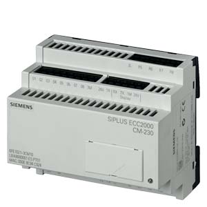
| Product brand name | | SIPLUS ECC2000 |
| charging current / typical | A | 16 |
| adjustable charging current | A | 6… 80 |
| Product description | | Actuation and monitoring of power components in the charging station, used for communication with the electric vehicle in acc. with IEC61851 |
| Standard / for security | | according to IEC 61010-1 / EN 61010-1 (2nd edition) or UL 61010-1 (2nd edition) |
| Protection class IP / on the front | | IP20 |
| Degree of pollution | | 3, to IEC/EN 61010-1 |
| Insulation voltage / with degree of pollution 3 / rated value | V | 230 |
| |
| Supply voltage: | | |
| Type of voltage / of supply voltage | | DC |
| Supply voltage | | |
| | V | 24 |
| | V | 18… 28 |
| Consumed current / for rated value of supply voltage | mA | 300 |
| |
| Communication: | | |
| Product function / bus-communication | | Yes |
| Protocol / is supported | | |
- communication to electric vehicle according to IEC 61851
| | Yes |
| | | Yes |
| |
| Display: | | |
| Number of LEDs | | 1 |
| Type of display | | |
| | | green, flashing / continuously illuminated, waiting for EF / charging active |
| | | red, flashing / flashing, error (see operating instructions) |
| |
| Inputs/ Outputs: |
| Number of interfaces / to IEC 61851 | | 1 |
| Number of digital inputs | | 8 |
| Type of voltage / of the input voltage | | DC |
| Input voltage | V | 0… 28 |
| Number of digital outputs | | 9 |
| Type of voltage / of the outputs | | DC |
| Output voltage | V | 18… 28 |
| Output current / at the digital output / for signal <1> / nominal value | A | 0.3 |
| Characteristic feature of the output / short-circuit protected | | Yes |
| |
| Auxiliary circuit: | | |
| Number of NO contacts / for auxiliary contacts | | 8 |
| Operating current / of auxiliary contacts | | |
| | A | 0.75 |
| | A | 0.75 |
| | A | 1 |
| |
| terminals | | |
| Contact assignment | | |
- of the bushing 1 at the PIN 1
| | L+24 V: DC 24 V connection (SELV) |
- of the bushing 1 at the PIN 2
| | M: DC 24 V connection (SELV) |
- of the bushing 2 at the PIN 1
| | FE: Functional ground (part of the vehicle interface, termination on connector in acc. with IEC61851) |
- of the bushing 2 at the PIN 2
| | PX: Proximity (part of the vehicle interface, termination on connector in acc. with IEC61851) |
- of the bushing 2 at the PIN 3
| | CP: Control pilot (part of the vehicle interface, termination on connector in acc. with IEC61851) |
- of the bushing 3 at the PIN 1
| | 1L: Root R1 ... R4 |
- of the bushing 3 at the PIN 2
| | R1: Relay output 1 |
- of the bushing 3 at the PIN 3
| | R2: Relay output 2 |
- of the bushing 3 at the PIN 4
| | R3: Relay output 3 |
- of the bushing 3 at the PIN 5
| | R4: Relay output 4 |
- of the bushing 4 at the PIN 1
| | 2L: Root R5 ... R8 |
- of the bushing 4 at the PIN 2
| | R5: Relay output 5 |
- of the bushing 4 at the PIN 3
| | R6: Relay output 6 |
- of the bushing 4 at the PIN 4
| | R7: Relay output 7 |
- of the bushing 4 at the PIN 5
| | R8: Relay output 8 |
- of the bushing 5 at the PIN 1
| | 24 V: Supply for 24 V outputs TR, O1 ... O8 |
- of the bushing 5 at the PIN 2
| | TR: Trip, 24 V output |
- of the bushing 5 at the PIN 3
| | RX: Receive line (RS232) |
- of the bushing 5 at the PIN 4
| | TX: Send line (RS232) |
- of the bushing 5 at the PIN 5
| | 1M: DC 24 V Minus (SELV/PELV) |
- of the bushing 5 at the PIN 6
| | 24 V: DC 24 V Plus (SELV/PELV) connection |
- of the bushing 6 at the PIN 1
| | O1: 24 V switching output 1 |
- of the bushing 6 at the PIN 2
| | O2: 24 V switching output 2 |
- of the bushing 6 at the PIN 3
| | O3: 24 V switching output 3 |
- of the bushing 6 at the PIN 4
| | O4: 24 V switching output 4 |
- of the bushing 6 at the PIN 5
| | O5: 24 V switching output 5 |
- of the bushing 6 at the PIN 6
| | O6: 24 V switching output 6 |
- of the bushing 6 at the PIN 7
| | O7: 24 V switching output 7 |
- of the bushing 6 at the PIN 8
| | O8: 24 V switching output 8 |
- of the bushing 6 at the PIN 9
| | 3M: reference point 24 V outputs O1 ... O8 |
- of the bushing 7 at the PIN 1
| | I1: 24 V input 1 |
- of the bushing 7 at the PIN 2
| | I2: 24 V input 2 |
- of the bushing 7 at the PIN 3
| | I3: 24 V input 3 |
- of the bushing 7 at the PIN 4
| | I4: 24V input 4 |
- of the bushing 7 at the PIN 5
| | I5: 24 V input 5 |
- of the bushing 7 at the PIN 6
| | I6: 24 V input 6 |
- of the bushing 7 at the PI
|