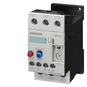
| | OVERLOAD RELAY, 14...20 A, 1NO+1NC, SIZE S0, CLASS 10, SCREW CONNECTION, FOR INDIVID. MOUNTING |
| |
| General technical details: |
| product brand name | | SIRIUS |
| product designation | | thermal overload relay |
| Protection class IP / on the front | | IP20 |
| Insulation voltage / with degree of pollution 3 / rated value | V | 690 |
| Installation altitude / at a height over sea level / maximum | m | 2,000 |
| Ambient temperature | | |
| | °C | -20… +70 |
| | °C | -55… +80 |
| | °C | -55… +80 |
| Relative humidity / during operating phase / maximum | % | 100 |
| Resistance against shock | | 8g / 10 ms |
| Impulse voltage resistance / rated value | kV | 6 |
| Active power loss / total / typical | W | 6 |
| Item designation | | |
- according to DIN 40719 extendable after IEC 204-2 / according to IEC 750
| | F |
- according to DIN EN 61346-2
| | F |
| Operating current / of the fuse link / rated value | A | 50 |
| Trip class | | CLASS 10 |
| Type of assignement | | 2 |
| type of protection | | DMT 98 ATEX G 001 |
| Size of overload relay | | S0 |
| Size of the contactor / can be combined / company-specific | | S0 |
| Protection against electrical shock | | finger-safe |
| |
| Main circuit: |
| Number of poles / for main current circuit | | 3 |
| Operating voltage / at AC-3 / rated value | | |
| | V | 690 |
| Service power / at AC-3 | | |
| | kW | 7.5 |
| Adjustable response current | | |
- of the current-dependent overload release
| A | 14… 20 |
| |
| Auxiliary circuit: |
| Contact reliability / of the auxiliary contacts | | acceptability for PLC control (17 V, 5 mA) |
| Number of NC contacts | | 1 |
| Number of NO contacts | | 1 |
| Number of change-over switches | | 0 |
| Operating current / of the auxiliary contacts / at AC-15 | | |
| | A | 3 |
| | A | 3 |
| | A | 3 |
| | A | 3 |
| | A | 2 |
| | A | 1 |
| Operating current / of the auxiliary contacts / at DC-13 | | |
| | A | 1 |
| | A | 0.22 |
| | A | 0.22 |
| | A | 0.11 |
| |
| Short-circuit: |
| Design of the fuse link / for short-circuit protection of the auxiliary switch / required | | fuse gL/gG: 6 A, quick: 10 A |
| |
| Installation/mounting/dimensions: |
| Built in orientation | | with vertical mounting surface +/-135° rotatable, with vertical mounting surface +/- 45° tiltable to the front and back |
| Type of mounting | | stand-alone installation |
| Height | mm | 97 |
| Width | mm | 45 |
| Depth | mm | 96 |
| Distance, to be maintained, to the ranks assembly | | |
| | mm | 0 |
| | mm | 0 |
| | mm | 0 |
| | mm | 0 |
| | mm | 0 |
| Distance, to be maintained, to earthed part | | |
| | mm | 0 |
| | mm | 0 |
| | mm | 0 |
| | mm | 0 |
| | mm | 6 |
| Distance, to be maintained, conductive elements | | |
| | mm | 0 |
| | mm | 0 |
| | mm | 0 |
| | mm | 0 |
| | mm | 6 |
| |
| Connection type: |
| Product function | | |
- removable terminal for auxiliary and control circuit
| | No |
| Design of the electrical connection | | |
| | | screw-type terminals |
- for auxiliary and control current circuit
| | screw-type terminals |
| Type of the connectable conductor cross-section | | |
| | | |
| | | 1x (1 ... 2.5 mm²), 1x (2.5 ... 10 mm²) |
| | | |
- with conductor end processing
| | 1x (1 ... 2.5 mm²), 1x (2.5 ... 6 mm²), 1x 10 mm² |
| |