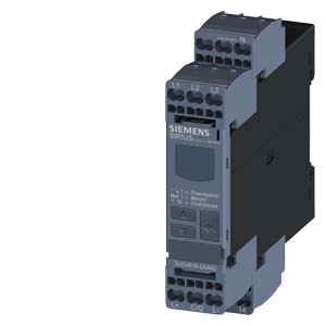
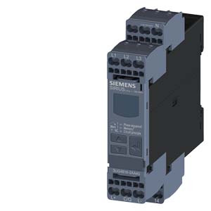
| | DIGITAL MONITORING RELAY FOR 3-PHASE VOLT. WITH N-COND FOR IO-LINK AC 50 TO 60 HZ 3X 160 TO 690V PHASE SEQUENCE, PHASE FAILURE PHASE ASYMMETRY UNDERVOLTAGE AND OVERVOLTAGE HYSTERESIS 1-20V NETWORK STABILIZATION TIME TRIPPING DELAY TIME 1 CO CONTACT, SPRING-LOADED CONNECTION |
| Product function | | Phase monitoring relay |
| |
| Measuring circuit: | | |
| Type of voltage / for monitoring | | AC |
| Number of poles / for main current circuit | | 3 |
| Measurable voltage | | |
| | V | 90… 400 |
| Adjustable voltage range | V | 90… 400 |
| Adjustable response delay time | | |
| | s | 0… 999.9 |
- with lower or upper limit violation
| s | 0… 999.9 |
| Relative adjustment accuracy | % | 0.2 |
| Relative metering precision | % | 5 |
| Precision of digital display | | +/-1 digit |
| Relative repeat accuracy | % | 1 |
| |
| General technical details: |
| Design of the display | | LCD |
| Type of display / LED | | No |
| Product function | | |
| | | Yes |
| | | Yes |
- phase sequence recognition
| | Yes |
- phase disturbance recognition
| | Yes |
| | | Yes |
- overvoltage recognition of 3 phases
| | Yes |
- undervoltage recognition of 3 phases
| | Yes |
- tension window recognition of 3 phases
| | Yes |
| | | Yes |
| | | Yes |
- open-circuit or closed-circuit current principle
| | Yes |
| Starting time / after the control supply voltage has been applied | ms | 1,000 |
| Response time / maximum | ms | 450 |
| Type of voltage / of the controlled supply voltage | | DC |
| Control supply voltage | | |
| | | |
| | V | 0… 0 |
| | | |
| | V | 0… 0 |
| | | |
| | V | 24… 24 |
| Working range factor supply voltage rated value | | |
| | | 1… 1 |
| Impulse voltage resistance / rated value | kV | 6 |
| Recorded real power | W | 2 |
| Protection class IP | | IP20 |
| Electromagnetic compatibility | | IEC 60947-1 / IEC 61000-6-2 / IEC 61000-6-4 |
| Resistance against vibration / according to IEC 60068-2-6 | | 1 … 6 Hz: 15 mm, 6 … 500 Hz: 2g |
| Resistance against shock / according to IEC 60068-2-27 | | sinusoidal half-wave 15g / 11 ms |
| Installation altitude / at a height over sea level / maximum | m | 2,000 |
| Conductor-bound parasitic coupling BURST / according to IEC 61000-4-4 | | 2 kV |
| Conductor-bound parasitic coupling conductor-earth SURGE / according to IEC 61000-4-5 | | 2 kV |
| Conductor-bound parasitic coupling conductor-conductor SURGE / according to IEC 61000-4-5 | | 1 kV |
| Electrostatic discharge / according to IEC 61000-4-2 | | 6 kV contact discharge / 8 kV air discharge |
| Field-bound parasitic coupling / according to IEC 61000-4-3 | | 10 V/m |
| Degree of pollution | | 2 |
| Ambient temperature | | |
| | °C | -25… +60 |
| | °C | -40… +85 |
| | °C | -40… +85 |
| Galvanic isolation | | |
- between entrance and outlet
| | Yes |
- between the voltage supply and other circuits
| | Yes |
| |
| Communication: | | |
| Type of voltage supply / via input/ output link master | | Yes |
| IO-Link transfer rate | | COM2 (38,4 kBaud) |
| Protocol / will be supported / IO-Link protocol | | Yes |
| Data volume | | |
- of the address range of the outputs / with cyclical transfer
| byte | 2 |
- of the address range of the inputs / with cyclical transfer
| byte | 4 |
| Point-to-point cycle time / between master and IO-Link device / minimum | ms | 10 |
| |
| Mechanical design: |
| Width | mm | 22.5 |
| Height | mm | 103 |
| Depth | mm | 91 |
| Built in orientation | | any |
| Distance, to be maintained, to earthed part | | |
| | mm | 0 |
| | mm | 0 |
| | mm | 0 |
| | mm | 0 |
| | mm | 0 |
| Distance, to be maintained, to the ranks assembly | | |
| | mm | 0 |
| | mm | 0 |
| |


