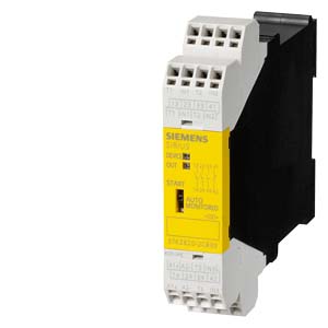
| | SIRIUS SAFETY RELAY WITH RELAY ENABLING CIRCUITS, 24 V AC/DC, 22.5MM, SPRING-LOADED TERMINAL, BASIC UNIT, AUTO START, MONITORED START INSTANTANEOUS: 3S, DELAYED: 0S, SIGNALING CIRCUIT: 1NC, MAX. ERR. CAT. EN954-1: 4 SIL: 3, PL: E SIL: 3, PL: E |
| |
| General technical details: |
| product brand name | | SIRIUS |
| product designation | | safety relays |
| Design of the product | | for EMERGENCY-STOP units |
| protection class IP / of the housing | | IP40 |
| Protection class IP / of the terminal | | IP20 |
| Protection against electrical shock | | finger-safe |
| Insulation voltage / rated value | V | 300 |
| Ambient temperature | | |
| | °C | -40… +80 |
| | °C | -25… +60 |
| Air pressure | | |
| | kPa | 90… 106 |
| Relative humidity | | |
| | % | 10… 95 |
| Installation altitude / at a height over sea level / maximum | m | 2,000 |
| Resistance against vibration / according to IEC 60068-2-6 | | 5 ... 500 Hz: 0,75 mm |
| Resistance against shock | | 15g / 11 ms |
| Impulse voltage resistance / rated value | V | 4,000 |
| EMC emitted interference | | IEC 60947-5-1, IEC 61000 |
| Installation environment relating to EMC | | This product is suitable for Class A environments only. It can cause undesired radio-frequency interference in residential environments. If this is the case, the user must take appropriate measures. |
| Item designation | | |
- according to DIN EN 61346-2
| | F |
| Number of sensor inputs | | |
| | | 1 |
| Type of the safety-related wiring / of the inputs | | single-channel and two-channel |
| Product feature / transverse contact-secure | | Yes |
| safety Integrated Level / according to IEC 61508 | | SIL3 |
| SIL claim limit (for a subsystem) / according to EN 62061 | | 3 |
| Performance level (PL) / according to ISO 13849-1 | | e |
| Category / according to ISO 13849-1 | | 4 |
| Probability of dangerous failure per hour (PFHD) / with high demand rate / according to EN 62061 | 1/h | 0.94E-9 |
| Average probability of failure on demand (PFDavg) / with low demand rate / according to IEC 61508 | 1/h | 0.831E-6 |
| T1 value / for proof test interval or service life / according to IEC 61508 | a | 20 |
| Number of outputs / as contact-affected switching element | | |
- as NC contact / for reporting function / instantaneous switching
| | 1 |
- as NO contact / safety-related / instantaneous switching
| | 3 |
- as NO contact / safety-related/ delayed switching
| | 0 |
| Number of outputs / as contact-less semiconductor switching element | | |
| | | |
| | | 0 |
| | | 0 |
| | | |
| | | 0 |
| | | 0 |
| Stop category / according to DIN EN 60204-1 | | 0 |
| |
| General technical details: | | |
| Design of the input | | |
| | | Yes |
| | | Yes |
| Design of the electrical connection / jumper socket | | No |
| Operating cycles / maximum | 1/h | 2,000 |
| Switching capacity current | | |
- of NO contacts of relay outputs
| | |
| | | |
| | A | 4 |
| | A | 0.2 |
| | A | 0.1 |
| | | |
| | A | 4 |
| | A | 4 |
| | A | 4 |
- of NC contacts of relay outputs
| | |
| | | |
| | A | 4 |
| | A | 0.2 |
| | A | 0.1 |
| | | |
| | A | 4 |
| | A | 4 |
| | A | 4 |
| Thermal current / of the contact-affected switching element / maximum | A | 5 |
| Electrical operating cycles as operating time / typical | | 200,000 |
| Mechanical operating cycles as operating time / typical | | 10,000,000 |
| Design of the fuse link / for short-circuit protection of the NO contacts of the relay outputs / required | | gL/gG: 10 A or quick-response: 10 A or MCB type B: 2 A or MCB type C: 1.6 A or SITOP select diagnostics module (order No.: 6EP1961-2BA00) |
| Resistance to direct current / of the cable / maximum | ? | 50 |
| Cable length / between sensor and electronic evaluation device / with Cu 1.5 mm? and 150 nF/km / maximum | m | 1,000 |
| Make time / with automatic start | | |
| | ms | 110 |
| Make time / with automatic start / after mains power cut | | |
| | ms | 110 |
| | ms | 170 |
| Make time / with monitored start | | |
| | ms | Назад в раздел
|